Thermal modelling of Buildings for Thermal Bridging Analysis
 Thermal modelling is a vital step in building design especially in today’s industry where efficiency is key. It gives architects, engineers and specifiers a clear picture of where heat loss can occur before construction begins, exposing the junctions where the building envelope is compromised by conductive materials such as steel or concrete.
Left unaddressed, these thermal bridges drive up energy consumption, reduce internal comfort and increase the risk of condensation and mould. Accurate modelling of architectural plans allows these weak points to be highlighted, with solutions selected at the initial design stage rather than discovered after completion.
HOW THERMAL MODELLING IS USED IN BUILDING DESIGN
Thermal modelling uses software-based simulation to map heat flow across a building’s junctions, calculating temperature gradients, U-values and heat loss at specific details such as balconies, parapets, column bases and slab edges.
It is a key design tool in the construction process which produces a thermal bridging diagram, detailing exactly where heat loss can occur, how severe it is and what level of interruption is needed to bring it back in line with performance targets.
Multi-storey residential building with cantilevered balconies showing a common location for cold bridging where structural connections penetrate the building envelope
USING THERMAL BRIDGING MODELS TO ASSESS HEAT LOSS
Thermal bridging models are essential for assessing the extent of a building’s heat loss, especially for projects targeting Passivhaus, Part L compliance, or a low psi-value strategy. By calculating the K and R values, you can work out the overall efficiency of the building and therefore help to specify the right products for your project. It also helps to identify the applications where heat loss occurs and where thermal break products need to be installed.
THERMAL MODELLING IN CONSTRUCTION DESIGN STAGES
Thermal modelling delivers the most value when it’s introduced early and revisited as the project develops through the design stages. For instance consulting a thermal model at RIBA stage 0-2 helps establish which junctions are likely to be problematic and informs the structural strategy before details are locked in.
By the time the construction has then progressed to technical design, models have become more detailed, feeding directly into U-value calculations, SAP/SBEM assessments and the specification of thermal break products at individual junctions.
Leaving thermal modelling until late in the design process, or treating it as a compliance box-ticking exercise, limits its effectiveness. Retrofitting a thermal break solution into a detail that’s already fixed is more difficult, albeit not impossible, but won’t be as effective as designing the junction around one from the outset.
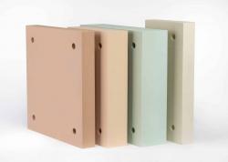
Armatherm 500 polyurethane thermal break pads in multiple density grades used to prevent cold bridging at structural connections in wall, floor and roof applications
INTERPRETING THERMAL BRIDGING DIAGRAMS FOR SPECIFICATION
Thermal bridging diagrams typically use a colour-graded temperature key to show how heat moves through a junction, with warmer colours highlighting areas of concentrated heat loss. For specifiers, the vital details to read are the location and severity of the thermal bridge, to ensure that these areas are addressed by implementing thermal break materials.